
Heckler Credenza Neo
This guide is also available as a printable PDF.
In the box
- 1 x Chassis (R1043)
- 1 x Front panel (F320)
- 1 x Backsplash & video bar mount (R1044)
- 1 x Backsplash wall template (K445-2)
- 1 x Chassis wall template (K445-1)
- 5 x Wall mount toggle (F037)
- 4 x Wall mount screw (F261)
- 4 x Wall mount washer (F035)
- 2 x Backsplash spacer screw (F263)
- 2 x Backsplash wall mount screw (F264)
- 8 x Rack mount screw (F938)
- 4 x Device mounting thumbscrew (F839)
- 4 x Device mounting thumbnut (F838)
- 4 x Push pin (F254)
- 1 x Velcro (F856)
- 4 x Wall mount spacer (P199)
- 2 x Backsplash mounting peg (P197+P198)
- 4 x Rack mount adapter (P200)
- 2 x Backsplash spacer (P201)
Determine the mounting position
Determine the preferred mounting height of your display.
Determine the height of the bottom edge of your display above the finished floor.
Place a long strip of masking tape at this height across the wall at your credenza-installation location.
Using a stud finder, mark the locations of your wall studs on this strip of masking tape.
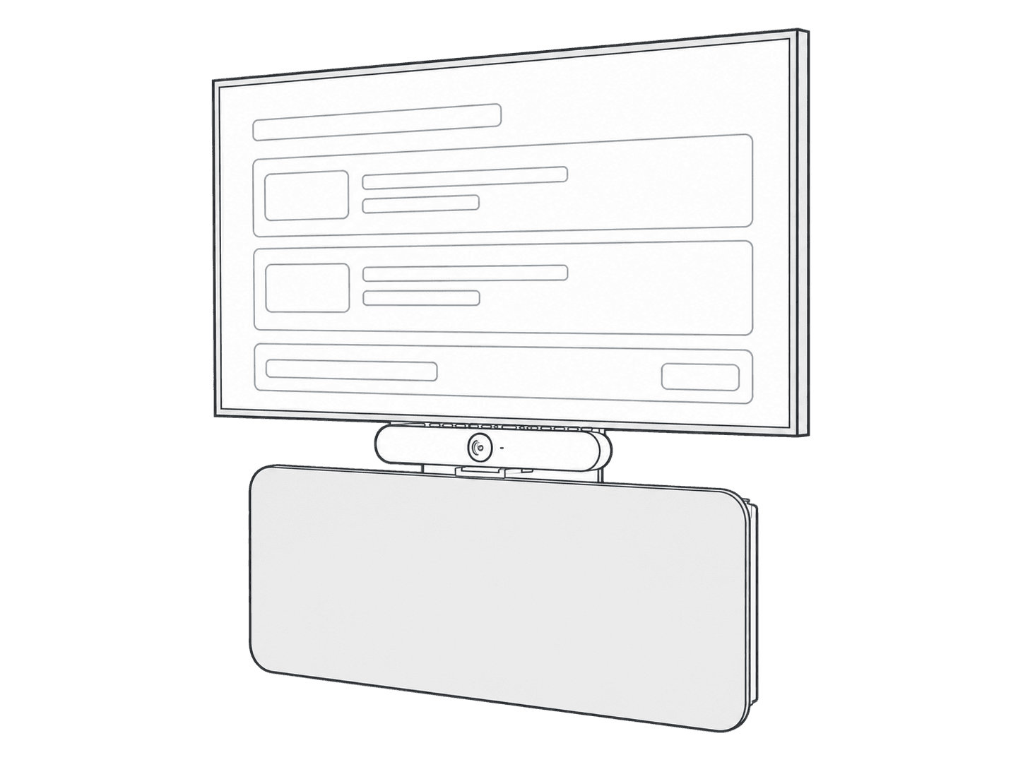
Use a level and the provided push pins to secure the backsplash wall template (item d) as shown, with its top edge slightly above the display-bottom height you marked. This allows the backsplash to hide the cables routed from Credenza Neo to the display.
Tuck the chassis wall template (item e) behind the backsplash wall template. Align the center triangles at one of the two height options, then pin the chassis template to the wall.
Fully level the chassis template.
Make sure the area highlighted in blue between the top of the chassis template and the display line provides enough clearance for your video conferencing gear. Confirm that Credenza Neo will cover the existing power outlet if needed.
Choose and mark four mounting holes in the corners that will avoid the wall studs. Credenza Neo is lightweight and we suggest using the provided wall toggles to mount it to drywall.
Install the wall mount spacers and backsplash mounting pegs
Match the wall templates pinned on the wall. Install four wall-mount spacers (item p) and two backsplash pegs (item q) at the corresponding locations on the chassis.
Holes highlighted in red are for wall mounting.
Rectangles highlighted in blue are for the backsplash mounting pegs.
Install the wall mount anchors
Remove wall templates. Install four wall mount toggle anchors (item f).
Install small devices and organize cables to the chassis
You can perform this step before or after mounting the chassis to the wall.
Use the Velcro strap included to mount devices and organize cables to the grid pattern on the credenza chassis. The hole pattern is 100 mm VESA grid and compatible with VESA mounting plates (not included).
Hang Credenza Neo chassis
Stand the Credenza Neo chassis upright. Insert two washers (item h) and two mounting screws (item g) through the top two mounting holes and spacers.
Lift the chassis, align the two upper screws with the wall anchors, and insert the screws into the anchors. Loosely fasten the top two screws.
Install the bottom two washers and screws. Then fully fasten all four screws.
Install video meeting camera
With screws provided (item i), install the wall spacers (item s) to the backsplash.
With included M4 thumbscrews (item l) and thumbnuts (item m), install your video conference gear’s wall mount bracket (not included) to the backsplash.
Slide the backsplash down behind the chassis, engaging its cutouts with both mounting pegs. Continue until the backsplash is fully seated on both pegs.
Optional: If you want to secure the backsplash to the wall, replace the mounting screws (item i) with wall mount screws (item j).
Organize cables from the chassis to the back of the Backsplash.
Connect the cables to the device and install the video conferencing gear on its wall-mount bracket.
Install rack mount devices
With screws provided (item k), install the rackmount adapters (item r) to the 19-inch rack mount device.
Hang the device from the elongated openings on either the left or right side of the chassis, highlighted in red below.
Install the front panel
Bring the front panel close to the chassis. Position its four discs slightly above the chassis cups, then lower the panel until all four discs are fully engaged in the cups.