
Heckler AV Credenza 4U
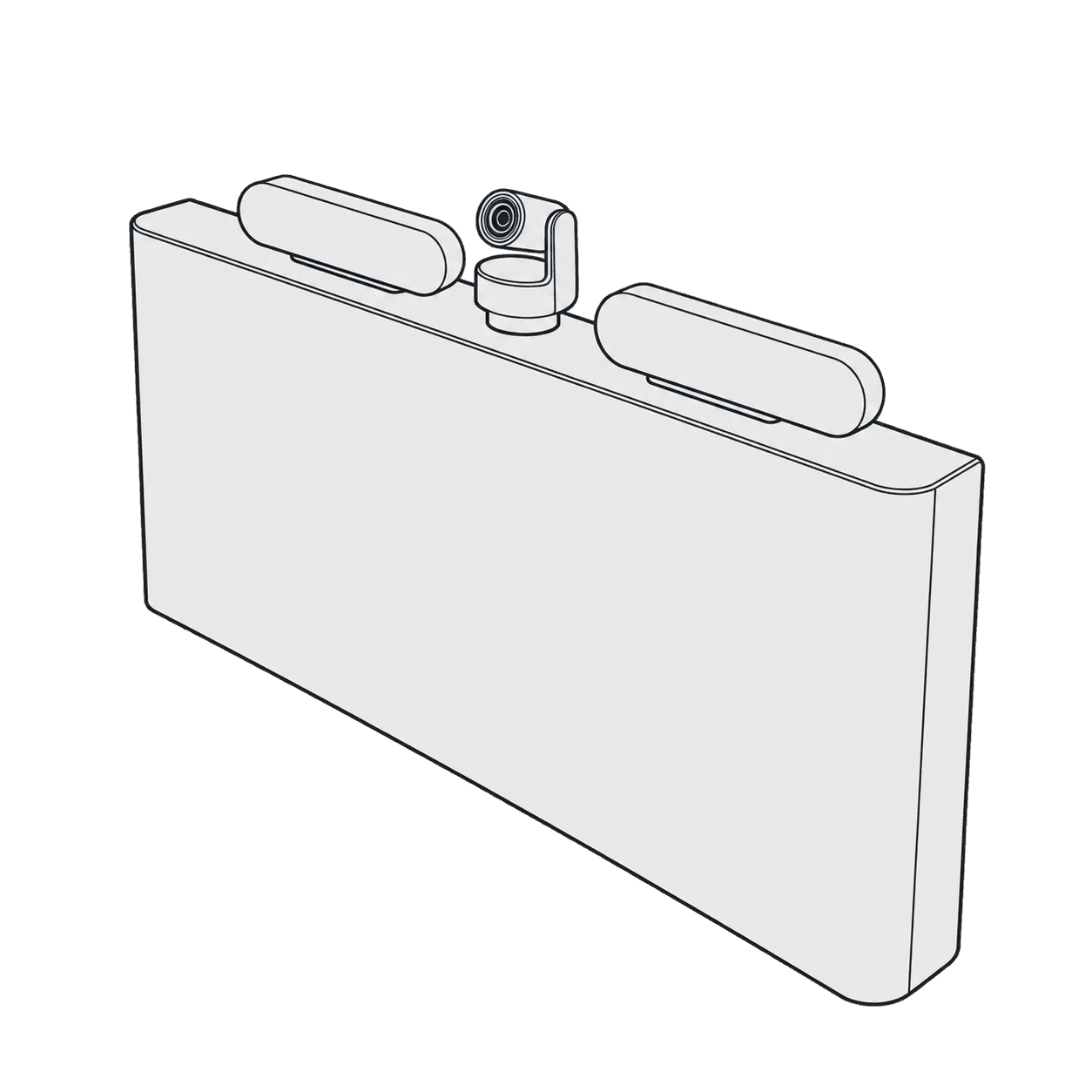
This guide is also available as a printable PDF.
In the box
- 1 x AV Credenza body (R572-BODYBG + 2xR572-BRACKETBG + R575-BG + R658-SS)
- 1 x French cleat (F960) with 2 x wing nut (F773)
- 1 x front panel (R572-PANEL)
- 1 x mounting bracket for All-in-one Appliance (R583) and 2 x screw (F956)
- 1 x mounting bracket for PTZ Camera (R584) and 2 x screw (F956)
- 1 x mounting bracket for Rally Bar & Rally Bar Mini (R585) and 2 x screw (F956)
- 2 x cable Chase (R574) with 4 x screw (F954 + F955)
- 1 x Heckler AV Wall Bracket Set (R576)
- 2 x thumb screws for Heckler AV Wall Bracket Set (F954 +F955)
- 2 x quick-release pins for Heckler AV Wall Bracket Set (F936)
- 2 x M4 thumb screw for All-in-one device mounting bracket (F839)
- 2 x M4 thumb nuts for All-in-one device mounting bracket (F838)
- 1 x screw for PTZ cameras mounting bracket (F775)
- 2 x screws for Rally Bar & Rally Bar Mini mounting bracket (F038)
- 1 x ball-end hex key for installing camera brackets (F957)
- 16 x cage nuts (F958)
- 16 x rackmount screws (F938)
- 3 x drywall-mounting screws (F945)
- 3 x drywall-mounting washers (F731)
- 4 x drywall-mounting wall anchors (F727)
- 6-foot roll of hook & loop strap (F947)
- 6 x strapping buckle (F751)
- 2 x key (F033)
Tools needed
- Level
- Tape measure
- Power drill
- Stud finder
- 3/4-inch drill bit
- Pen
Install the French cleat
Mark the center of the AV Credenza installation location, 30 inches above the finished floor.
Mark your wall stud positions along the length of the cleat, 30 inches above the finished floor.
Starting at the center of the cleat, drill and install the first wall anchor.
Fasten the cleat to the wall at this center position.
Use a level, then mark two additional mounting points using the cleat as your hole template.
Install two additional wall anchors and fasten the cleat to those positions.
How to install a Snaptoggle wall anchor
1. Hold metal channel flat alongside plastic straps & slide channel through the hole. Minimum clearance behind wall: only 1-7/8” 2. Hold ends of straps together between thumb & forefinger and pull toward you until channel rests behind wall. Ratchet cap along straps with other hand until flange of cap is flush with wall. 3. Place thumb between straps at wall. Push thumb side to side, snapping off straps level with flange of cap. 4. Place item over flange. Insert bolt and tighten until snug against item, then stop. Use machine screw or bolt to match thread in metal channel.
Install 19-inch rack components
Place AV Credenza on its back on a tabletop.
Install the provided cage nuts.
Slide components in place and fasten with provided rack screws.
Install small devices and organize cables.
Cut the provided hook & loop straps to length as needed for strapping components and cable management.
Strap components and cables to the grid of large rectangular holes on the rear and bottom surfaces of the credenza body.
Fasten NUCs and other VESA-compatible devices to the VESA-compatible M4 clearance holes located between the large rectangular holes. M4 mounting hardware is not included.
Hang AV Credenza body
Using two people, carefully lower the AV Credenza onto the French cleat.
Fasten AV Credenza to the French cleat using the wing nuts provided.
Install video meeting camera
Install PTZ Camera Mount bracket
Fasten the camera mount to your camera using the appropriate hardware. A 1/4”-20, 5/16” long screw is provided for your convenience but may not be compatible with your camera.
Slide the bracket’s mounting screws into the horizontal keyhole slots on the back wall of the credenza.
Tighten the screws with the provided ball-end hex key.
Install Rally Bar or Rally Bar Mini bracket
Fasten the bracket to Rally Bar with the 1/4-20 screws provided.
Slide the bracket’s mounting screws into the horizontal keyhole slots on the back wall of the credenza.
Tighten the screws with the provided ball-end hex key.
Install All-in-one Appliance bracket
Fasten the bracket to All-in-one Appliance with the M4 thumb screws and M4 thumb nuts provided.
Slide the bracket’s mounting screws into the horizontal keyhole slots on the back wall of the credenza.
Tighten the screws with the provided ball-end hex key.
Install cable chases (optional)
Unfasten the thumbscrews on the cable chase.
Install the cable chases and channel the display cables.
Fasten the thumbscrews.
Attach the front panel
Lower the front panel onto the body by aligning the ball joint on the panel to the cutout on the main body.
Close the panel until the posts on the top left and right meet the body.
Slightly lift up the panel and let the posts drop into the hooks on the main body.
Use the provided keys to turn the cam lock on the underside of the credenza body.
Optional: Install onto Heckler AV Wall Structure
Install Heckler AV Wall bracket set to the AV Wall structure at the preferred height.
Insert the quick-release pins from the back to lock the brackets.
Install the Credenza body to the bracket set by engaging the rear hooks to the posts on the bracket.
Fasten the thumbscrews to lock the Credenza body to the brackets.