
Heckler Framework Structure Assembly
This guide is also available as a printable PDF.
Tools needed
- A carpeted floor, moving blanket, or drop cloth
- A bubble or spirit level or digital level tool
- A laser line level
- Masking tape
- A quality steel and wood stud finder
- A pencil or pen
- Post-its (these are optional)
- A power drill with a small bit for pilot holes as well as a 3/4-inch step bit
Assembly Video
The print edition uses the source assembly illustrations below; these are not frames from the overview video.
Assemble the structure
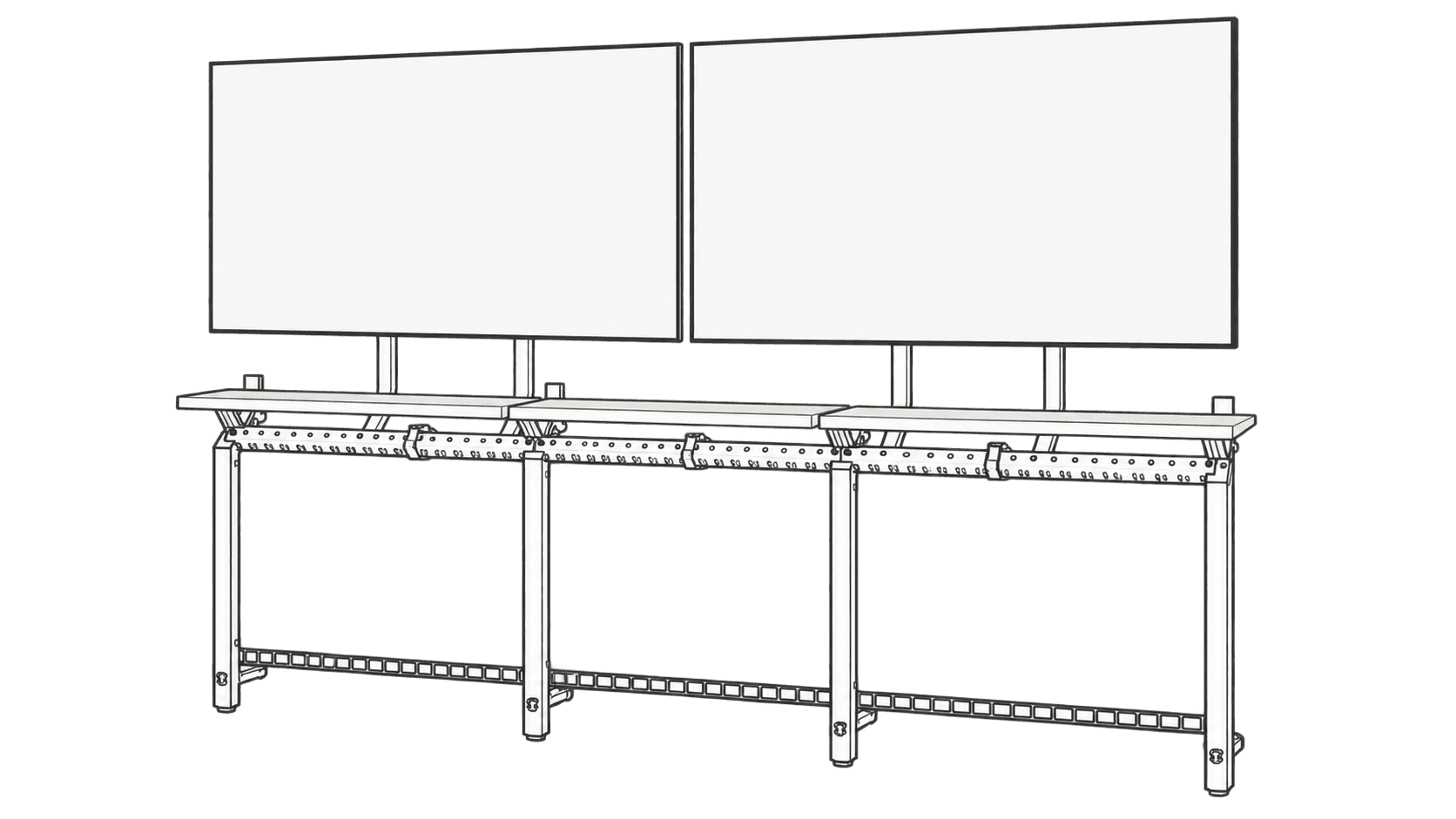
Place the legs and beams in the arrangement shown below.
Working left to right, slide the end of the first leg through the end of the first beam as shown.
Once fully seated, the bolt hole in the leg will align with the bolt hole in the beam.
Insert a lock nut into the hex-shaped hole on the rear of the beam and hold it in place with your thumb.
Insert an assembly bolt through the front of the leg and beam, and loosely thread the bolt into the lock nut by hand. There is no need to fully tighten it at this point. You’ll tighten these bolts once the structure is upright.
Repeat this process for each of your legs.
Install wall anchors
Raise the structure upright and lean it carefully against the wall in its intended final location. Large structures will require multiple people for this step.
Place masking tape on the wall corresponding to each leg’s position.
Rest the structure back on the floor.
Measure the anchor height from the floor and place the laser line on that mark.
Place masking tape across this line.
Using an appropriate stud finder, mark the tape with the left and right edges of each wall stud along the length of your structure.
Select the stud that is closest to center between each pair of legs. Mark your anchor location centered on this stud, at the height of your laser line. Repeat this for each span between legs, but don’t put away your laser level. We’ll be using it again soon.
Install a toggle anchor.
How to install a toggle anchor
1. Hold metal channel flat alongside plastic straps & slide channel through the hole. Minimum clearance behind wall: only 1-7/8” 2. Hold ends of straps together between thumb & forefinger and pull toward you until channel rests behind wall. Ratchet cap along straps with other hand until flange of cap is flush with wall. 3. Place thumb between straps at wall. Push thumb side to side, snapping off straps level with flange of cap. 4. Place item over flange. Insert bolt and tighten until snug against item, then stop. Use machine screw or bolt to match thread in metal channel.
Fasten a supplied eyelet lag bolt and washer to the toggle anchor until snug. Repeat this process for each of your anchor locations.
Install Structure
Install leveling feet and wall spacers on the legs
For a consistent starting position, check that your leveling feet are fully screwed in.
Insert the spacer and press downward until fully seated. Note that the “Down Side” text on the part should face downward.
Install Lashing Straps
To prevent the structure from tipping forward at this step, loosely install the lashing straps.
Raise the structure upright. With the buckle on top, run the strap under the beam, up through the eyelet lag bolt, and back over the beam. Insert the strap into the buckle according to the manufacturer's guidance. Keep the strap loose for now so you can install the shelf supports in the next step.
Install Shelf Supports
Slide each shelf support into the top of the leg as shown.
Using the provided hex key, fasten the shelf support to the leg from the back using the provided bolt.
Twist the wall spacer adjustment knob on the shelf support to ensure it is fully retracted.
Repeat the process for each leg.
Extend sliding panel dividers as needed.
Each shelf support features these two integrated sliding panel dividers.
Install Crossbars
Install a crossbar between each pair of legs as shown, ideally at their lowest possible position.
Fully tighten the screws fastening each leg to the beam.
Push your structure against the wall so that all adjustment knobs on the leg spacers and the shelf support spacers make contact with the wall.
Use your laser level and set the laser line at the top edge of your beam. Adjust your leveling feet from left to right, until the laser line sits uniformly across the entire length of the beam.
Check your beam for straightness.
Snug your lashing straps but do not fully tighten.
Stand to one side of your structure, then peer down the length of the beam. Check your beam for straightness.
Working from left to right along your structure, adjust the knobs on the shelf supports as needed to straighten your beam.
Use a level to verify that the front face of each of your legs is vertical. To do so, push the leg toward the wall to ensure the lower spacer on the leg is making contact with the wall. Check the front face of the leg for plumb. Turn the adjustment knob on the lower spacer as needed. Working left to right, repeat this for each leg.
Install Single Display
Install display columns
Find the center of your structure. For a structure with an odd number of bays, the center will be the center socket of the center bay.
For a structure with an even number of bays, the center will be the center leg.
Each beam socket is spaced 50 mm on center. Identify which sockets on the beam to use based on your display’s horizontal VESA pattern.
Install the rear bumper on the column so it will make light contact with the wall.
Slide the column into the socket selected.
Ensure these tabs protrude through the bottom slots of the beam and that the columns are fully seated.
Fasten the column in place with a bolt and lock nut.
Use a level to quickly check that the column is plumb.
Install the backsplash panel support to the column. Identify the third keyhole from the bottom of the column and pop it into place.
Repeat this process for your second column. Tighten all lashing straps.
Prep your display for mounting.
Fasten the supplied mounting set screws into your display by hand. Both M6 and M8 mounting screws are provided.
Fasten the display anchors onto the set screws until the anchors are snug against the surface of the display.
For convenience, it’s a good idea to attach your power, HDMI, and Ethernet cables to the display before you mount the display.
Determine Column Mounting Holes
Measure the distance from the bottom edge of the display to its upper VESA mounting holes.
Sum up:
- the height of the shelf (40 inches for Tall Legs, 31 inches for Short Legs)
- the height for video bar or PTZ camera (typically 6 to 8 inches)
- the distance from the bottom edge of the display to its upper VESA mounting holes (measured during the previous step).
Measure this distance from the floor and place a small piece of masking tape on the outer side of the column, aligned with the closest mounting hole. The tape will be a helpful indicator while the display is lifted into place. Repeat this for the second column.
Lift and Lower Display
Approach the columns, align the upper display anchor with your mark, insert all four anchors into the opening of the keyholes, then lower until fully seated.
Route Cables Behind Beam
Guide any cables or connections down the back and behind your beam. They’ll be hidden once you put your shelves and backsplash panels in place.
Install Multiple Displays
Measure the distance from the outside edge of your display to its nearest VESA mounting point.
Find the center of your structure. Mark this distance away from the center of your structure. Select the column socket just outside this measurement.
Install your first column.
Measure the distance between the horizontal VESA mounting points on your display.
Transfer this measurement from your first column to locate the socket for your second column. Install your second column.
Mirror this process and install the second set of columns.
Install both displays using the single-display installation steps described above.
Install Shelves
Place shelves on a soft surface with the front edge of the shelf facing you. Note that Outer Shelves are longer than Inner Shelves.
Install your shelves from left to right. Your first shelf will be an outer (or longer) shelf. To position the first outer shelf correctly, align its right edge with the center of the shelf support.
Insert the tabs on the rear of the shelf into the narrow tab slots in the shelf support.
Magnetically place the first shelf.
Repeat this process to place each shelf. For the three-bay build shown, the next shelf will be an Inner Shelf, followed by an Outer Shelf.
Check to ensure your shelves are straight and aligned.
Stand at the left side of your structure and look down the length of your shelves. If any shelves are out of alignment, adjust the shelf support wall spacers as needed. You may need to adjust the lashing straps while doing so.
Install Panels
Backsplash Panel Installation
Install a backrest on each shelf support. These keep your backsplash panels fully upright.
Install the center Backsplash Panel first by sliding it up and behind your display with all cables running behind the panel.
If a column is positioned behind the backsplash panel, insert the panel’s upper edge into the column mounted supports and down into the backsplash channel on your shelf supports.
Check to ensure the sliding panel dividers are engaged. These ensure consistent gaps between each panel.
Work outward in each direction and install the other Backsplash Panels.
End Cap Panel Installation
Twist the end cap panel mounts into the upper and lower holes on the outer face of the left and right legs.
Press the End Cap Panels into position.