
Heckler Lectern 6U
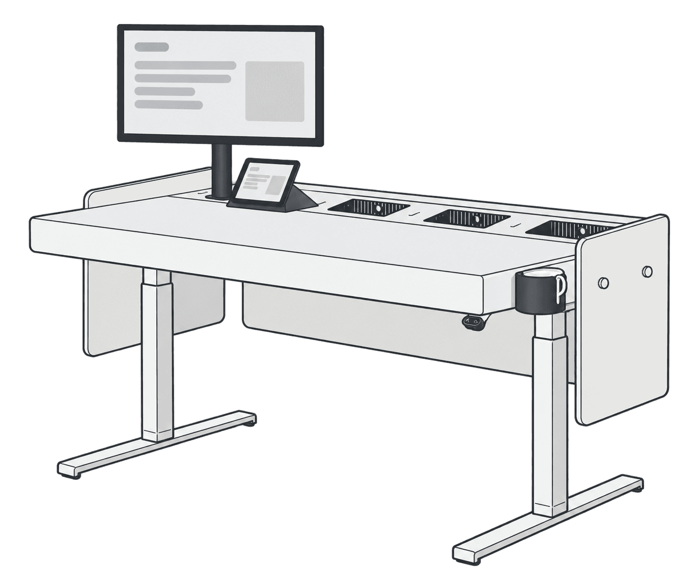
This guide is also available as a printable PDF.
In the box
- 1 x Heckler Lectern Body
- 2 x Sit/Stand Lift Column
- 1 x Assembly hardware bag
- 1 x Sit/Stand Controller
- 1 x Sit/Stand Control Switch
- 1 x Anti Collision Sensor
- Sit/Stand Feet
Assembly Hardware Bag List
Baggie 1
“Modesty Panel DO NOT DISCARD”
| P015 | Modesty Panel Spacer | 8 |
| P016 | Screw Cap | 8 |
| F993 | Mounting Screw | 8 |
Baggie 2
“Cable Management Accessories”
| P052 | Cable management part | 2 |
| F106 | Alcohol pad | 2 |
| F854 | Velcro Strip | 1 |
“Sit/Stand Leg Hardware”
| F987 | Sit/Stand Leg Assembly Screw | 14 |
| F989 | Sit/Stand Leg Assembly Plastic Washer | 14 |
| F674 | Hex L-Key | 1 |
“Sit/Stand Feet Hardware”
| Sit/Stand Feet Hardware | 8 | |
| F523 | Hex L-Key (Use for LINAK feet mounting to LINAK Leg) | 1 |
“Lectern Key”
| F985 | Lectern Key | 1 |
Tools needed
- clippers, scissors, or zip tie cutters
Unpack accessories
Unstrap and remove the bag located within the beam of the lectern. This bag contains your hardware and the keys to the lectern.
Install the lifting columns
High-quality Linak-brand sit/stand components are used with Heckler Lectern. The manufacturer’s full instructions for the DL5 columns with CBD6S controller can be found here:
Find the part bag labelled “Sit/Stand Leg Hardware”
Fasten the first column to beam on the underside of the lectern using four M6 screws and washers. Do not fully tighten the 4 screws and leave the two positions on the short side for later installation.
Repeat for the second column.
Install the feet to the lifting columns
Fasten each foot to the bottom of each lifting column using the M8 screws packaged with the foot parts.
Fasten each of the four leveling feet included in the T508-WT box. If you are installing casters, skip to the next step
Install the casters (optional)
For complete caster installation instructions, please refer to H904 Casters.
Upright the lectern
With the lectern body still resting inside the box bottom, and one person positioned at each end of the lectern, rotate the lectern and the box bottom to bring the lectern’s feet near the ground.
With one hand on the lifting column and one hand gripping the hole pattern on the underside of the lectern, carefully upright the lectern with the box bottom remaining in place to protect the lectern.
Carefully lift the box bottom from the lectern.
Install remaining screws and fasten all screws
Opening and removing the desktop
Cut and discard the zip ties located on the underside left and right corners of the desktop.
Locate the cam lock on the underside surface on the right-hand side of the lectern. Unlock the lectern desktop.
Open the desktop
If your lectern has casters installed, engage the brake on all four casters.
Stand facing the front edge of the desktop. Grip the underside front edge of the desktop with both hands then lift upwards and pull forward simultaneously.
Close the desktop
If your lectern has casters installed, engage the brake on all four casters.
Stand facing the front edge of the desktop. Grip the underside front edge of the desktop with both hands then push forwards slowly. Carefully lower the desktop.
Removing the desktop
With the desktop open, remove the four nylon wing nuts from its underside.
Carefully lift the desktop from the desktop hinges. Set the desk on a soft surface.
Reverse this process to reinstall the desktop.
Install Linak height adjustment components and wiring.
Slide and click the Linak height adjustment switch to its mounting bracket.
Connect the Linak controller to each lifting column.
Connect the Linak Anti-collision sensor to the Linak Controller.
Connect the Linak controller power cable.
Install rack-mount components
The interior of the lectern body contains three 2RU 19-inch component racks, for a total of 6RU of internal storage.
Grounding
To connect lectern's grounding lug to your power distribution unit (PDU), follow these steps:
1. Locate the grounding lug on the PDU. This is usually a metal stud or screw that is connected to the PDU's grounding circuit. 2. Remove the nut or screw that secures the grounding lug. 3. Insert the end of the grounding cable (not included) into the grounding lug. 4. Tighten the nut or screw to secure the cable in place. Make sure it is snug, but do not overtighten it. 5. Ensure that the other end of the grounding cable is securely attached to one of the lectern’s grounding lugs. 6. Verify that the grounding circuit is functioning properly by using a multimeter to test for continuity between the PDU's grounding lug and the grounding point.
It's important to note that proper grounding is essential for the safe and reliable operation of your equipment. If you are unsure about any aspect of the grounding process, or if you encounter any difficulties, consult a qualified electrician or IT professional for assistance.
Configure your console
The rear portion of Heckler Lectern’s desktop is called the console. The console features:
- four small slots for mounting display arms, lights, and document cameras,
- three console insert areas for installing touchscreens, courtesy IO, microphone chargers, and more.
The back wall of the console features:
- three 80mm exhaust fan mounting positions.
- Six grommeted cable pass-through holes with caps.
Install console inserts
With the Heckler Lectern and its console inserts, you can easily create fully integrated lecterns using your preferred components. It's fast and easy to replace one console insert with another, which reduces the effort required to update your technology.
Refer to the user guide for your specific console inserts.
Do you need Heckler to create a new console insert?
Heckler console inserts are designed to customize your lecterns to your device preferences. This allows for easy updating of devices in the future. If you have an idea for a console insert that we don't offer, please contact us at service@heckler.com.
Create your own console inserts
If you want to design your own console inserts, you are welcome to do so. Console inserts can be easily produced via additive manufacturing using popular 3D printers. Contact service@heckler.com to obtain 3D models that you can modify to quickly create tech inserts that are perfect for your needs.
Mount display arm
The console of the Lectern has four mounting positions that can be used for display arms, document cameras, microphone arms, lighting mounts, and other accessories.
Remove the cap at your desired display-mounting location. Unlock and open the desktop to gain access to the underside of the mounting position. Follow the desktop-grommet-mounting instructions for your display arm to mount the arm to the console.
Cable management
Cable management within the lectern body
The lectern floor features a hole grid that can be used to strap cables.
Connecting a cable loom
You have multiple options for routing power and data cables from the lectern to the floor. If your room already has cable looms installed, you can anchor them to the grid under the lectern using Velcro straps or zip ties.
The loom can hang directly to the floor or you can anchor it to the lifting columns using the included cable anchors.
To install the lifting column cable anchors:
Clean the mounting surface with the provided isopropyl alcohol pad
Adhere the first anchor to the top of the stationary section of the lifting column using the provided 3M Command strip
Adhere the second anchor directly under the first anchor, near the bottom of the stationary section, of the lifting column using the provided 3M Command strip
Press the Up button to raise the lectern to its tallest position.
With the lectern in its tallest position, tether the loom to the anchors using the provided white Velcro tape.
Lower the lectern to its shortest position. Check to ensure slack is present in the loom.
Raise the lectern to its tallest position. Check to ensure slack is present in the loom and no strain is present where the loom connects to the underside of the lectern.